Piler System
Program-Transformation.Org: The Program Transformation Wiki
The PILER Decompilation System
- Interpretation of the subject (input) program's "commands" (the Interpreter)
- Analysis of the source program for function and data usage (the Analyser)
- Expression of the source program in the target language (the Converter)
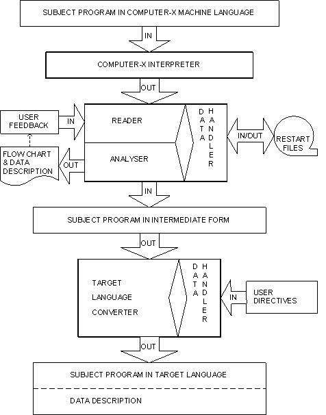 A reproduction of Figure 2 of [Barb74], complete with upper case text.
The "interpreter" phase
The "interpreter" phase (not a program interpreter as we would use the term now) ran on the source machine, and has the input program loaded with it (just insert the cards into the deck!). The interpreter therefore used the loader and operating system of the source machine. The output of this phase (the first intermediate representation) was called Micro Form. This was supposed to be general, but reflected the narrow variety of machines at that time. Instead of making this a clean interface, they decided that Micro Form could be in any form that was convenient for the interpreter phase, as long as the subroutine RMR (Read Microform Record) in the Analyser phase could read it. The interpreter phase had three subphases: loader, analysis (not the same as the analysis phase; this subphase just attempts to separate code from data), and interpretation. The analysis subphase generated several data structures: a memory map, symbol table, subroutine table, data reference table, and an input/output buffer table. It seems that the opcode field was often used to decide if a word was instruction, data, or I/O control. "Secondary microforms" were appended for indexed instructions and the like.Micro Form
Microform was the low level intermediate representation. It was 3 address.The analyser phase
This phase could be run on any computer, not necessarily the source or target machines. The basic procedures were (from [Barb74]):- First level analysis. Memory mapping for separation of program instructions and data. Division of program into logical blocks. Preliminary "timing analysis". Flagging of indexed or modified branch addresses and operation codes. Subroutine analysis.
- Data analysis. Historical use of data locations and registers. Formats of data.
- Second level analysis. Analysis of modified addresses and operation codes and completion of first level analysis and data analysis for any additional segments. Program reduction.
- "Timing analysis". Assignments of computational priorities based on data usage requirements.
- Third level analysis. Reduction of program to functional level, rather than instructive level.
- Preparation of flowchart blocks.
- Preparation of Intermediate Form subject program.
- Reader (contains the Read Microform Record (RMR) subroutine)
- Data handler
- Analyser
- Flow charter
- Program modifier (accepts directives from the user to modify the subject program).
Intermediate Form
Intermediate Form is the high level intermediate representation. It was designed with the following languages as likely targets: FORTRAN, COBOL, ALGOL, JOVIAL, and PL/1. To give a flavour, here are some of the codes: Mathematical Symbols001 Plus 010 Reciprocal 002 Minus 011 Exponent 003 Unary minus 012 Boolean OR 004 Inverse subtract 013 AND 005 Multiply 014 EXTRACT 006 Divide 015 EXCLUSIVE OR 007 Inverse divide 016 EQUIVALENT 020 Equals 017 CONDITIONALInternal Functions
140 I/O      Subfields
             01  Test        10  Input
             02  Position    20  Close
             04  Output      40  Open

040  Round               050  Modulo
041  Normalise           051  Remainder
042  Adjoin              052  Absolute value
043  Largest integer     053  Set ON (-,1)
044  Smallest integer    054  Set OFF (+,0)
045  Maximum
046  Minimum
100  Test
101  Compare             Subfield
102  Search              01  Match
103  Sort                02  Mismatch
104  Enter               03  Max value in array
105  Move                04  Min value in array
                         05  Greater than comparand
                         06  Greater or equal to comparand
                         07  Less or equal to comparand
                         10  Between limits of 2 comparands
                         11  Next lower than comparand
                         12  Next higher than comparand
120 Internal procedure
130 External procedure
Operand types:
01    Constant
02    Literal
04    Variable
05    Subscripted variable
06    Subscript
10    Function
11-16 Parameters as 01-06 above
20    I/O list
30    Format list